2017/02/12

Notes About Optimization of Machine Learning

Partial Derivative
In mathematics, a partial derivative of a function of several variables is its derivative with respect to one of those variables, with the others held constant (as opposed to the total derivative, in which all variables are allowed to vary). Partial derivatives are used in vector calculus and differential geometry.


Optimization Goal
The loss function lets us quantify the quality of any particular set of weights W. The goal of optimization is to find W that minimizes the loss function.


How to Optimize
Strategy #3: Following the Gradient

In one-dimensional functions, the slope is the instantaneous rate of change of the function at any point you might be interested in. The gradient is a generalization of slope for functions that don’t take a single number but a vector of numbers. Additionally, the gradient is just a vector of slopes (more commonly referred to as derivatives) for each dimension in the input space.  The mathematical expression for the derivative of a 1-D function with respect its input is:


When the functions of interest take a vector of numbers instead of a single number, we call the derivatives partial derivatives, and the gradient is simply the vector of partial derivatives in each dimension.

There are two ways to compute the gradient: A slow, approximate but easy way (numerical gradient), and a fast, exact but more error-prone way that requires calculus (analytic gradient)


Gradient Descent
Now that we can compute the gradient of the loss function, the procedure of repeatedly evaluating the gradient and then performing a parameter update is called Gradient Descent.


Mini-batch gradient descent
In large-scale applications (such as the ILSVRC challenge), the training data can have on order of millions of examples. Hence, it seems wasteful to compute the full loss function over the entire training set in order to perform only a single parameter update. A very common approach to addressing this challenge is to compute the gradient over batches of the training data. For example, in current state of the art ConvNets, a typical batch contains 256 examples from the entire training set of 1.2 million


Reference
http://cs231n.github.io/optimization-1/

2017/02/09

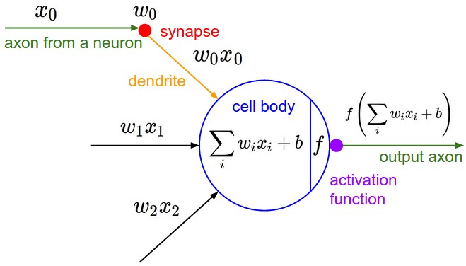
A Neuron In a Neural Net

This is an neural network


This a Neuron and Neuron Model


b: Bias
w: Weight
f: Activation function

Activation Function Example
- ReLU (Rectified linear unit)
- Leaky ReLU
- Sigmoid
- Tahn
-


2017/01/17

Complex scattering example

What code/data must be placed in a root region of a scatter file?

The initialization code/data from within the C library that does the copying from load to execution addresses must be placed in a root region (i.e. one which executes at its load address). This is because this code/data cannot itself be copied. This means that the scatter description file must have at least one root region that must contain:
  • The copying code from the library member called __main.o.
  • Sections named Region$$Table and ZISection$$Table which contain the addresses of the code/data to be copied. These sections are generated by the linker so they do not have a corresponding object file (so * must be used when placing these in a scatter file).
If these sections named Region$$Table and ZISection$$Table are not placed in a root region then the linker will report:
Error: L6202E: Section Region$$Table cannot be assigned to a non-root region.
Error: L6202E: Section ZISection$$Table cannot be assigned to a non-root region. 
In many cases this code/data may be placed in a root region by use of a wildcard *(+RO) that gathers all non-explicitly placed code/data. However in some circumstances, this wildcard may need to be placed in a non-root region, in which case a scatter file similar to the one below may be used.
Example scatter file for ADS and RVCT 2.0:
LOAD_FLASH 0x04000000 0x80000   ;start address and length
{
    EXEC_FLASH 0x04000000 0x80000
    {
        init.o (Init,+FIRST)    ; remap & init code
        __main.o (+RO)          ; copy code
        * (Region$$Table)       ; RO/RW addresses to copy
        * (ZISection$$Table)    ; ZI addresses to zero
    }
    EXEC_32bitRAM 0x0000 0x2000
    {
        vectors.o (Vect,+FIRST) ; vector table
        int_handler.o (+RO)     ; interrupt handler
    }
    EXEC_16bitRAM 0x2000 0x80000
    {
        * (+RO)                 ; ## all other RO areas ##
        * (+RW,+ZI)             ; program variables
    }
} 
For RVCT 2.1 and later, an alternative way is to specify these sections using InRoot$$Sections:
LOAD_FLASH 0x04000000 0x80000   ;start address and length
{
    EXEC_FLASH 0x04000000 0x80000
    {
        init.o (Init,+FIRST)    ; remap & init code
        * (InRoot$$Sections)    ; using InRoot$$Sections
    }
    ...
} 
An application's initial entry point must also be rooted. If the initial entry point is not in a root region, the link will fail with an error such as:
Error: L6203E: Entry point (0x08000000) lies within non-root region EXE_FLASH. 


Reference:
http://infocenter.arm.com/help/index.jsp?topic=/com.arm.doc.dui0474g/BABEJHII.html

http://www.keil.com/support/man/docs/armlink/armlink_pge1362065974588.htm

http://infocenter.arm.com/help/index.jsp?topic=/com.arm.doc.faqs/ka3552.html

2017/01/16

ARM Scatter File Explain

Bookmark below simple straight forward explaining
http://www.keil.com/support/man/docs/armlink/armlink_pge1362065973150.htm
Simple scatter-loaded memory map
7.1.6 Scatter-loading images with a simple memory map
For images with a simple memory map, you can specify the memory map using only linker command-line options, or with a scatter file.
The following figure shows a simple memory map:
Figure 7-1 Simple scatter-loaded memory map

Simple scatter-loaded memory map

Simple scatter-loaded memory map


The following example shows the corresponding scatter-loading description that loads the segments from the object file into memory:

LOAD_ROM 0x0000 0x8000       ; Name of load region (LOAD_ROM),
                             ; Start address for load region (0x0000),
                             ; Maximum size of load region (0x8000)
{
    EXEC_ROM 0x0000 0x8000   ; Name of first exec region (EXEC_ROM),
                             ; Start address for exec region (0x0000),
                             ; Maximum size of first exec region (0x8000)
    {
        * (+RO)              ; Place all code and RO data into
                             ; this exec region
    }
    SRAM 0x10000 0x6000      ; Name of second exec region (SRAM),
                             ; Start address of second exec region (0x10000),
                             ; Maximum size of second exec region (0x6000)
    {
        * (+RW, +ZI)         ; Place all RW and ZI data into
                             ; this exec region
    }
}

2016/11/20

PCIE Configuration & Enumeration

Configure Space Addressing
One of the major improvements the PCI Local Bus had over other I/O architectures was its configuration mechanism. In addition to the normal memory-mapped and I/O port spaces, each device function on the bus has a configuration space, which is 256 bytes long, addressable by knowing the eight-bit PCI bus, five-bit device, and three-bit function numbers for the device (commonly referred to as the BDF or B/D/F, as abbreviated from bus/device/function)


About Device ID and Vendor ID
The Device ID (DID) and Vendor ID (VID) registers identify the device (such as an IC), and are commonly called the PCI ID. The 16-bit vendor ID is allocated by the PCI-SIG. The 16-bit device ID is then assigned by the vendor. There is an ongoing project to collect all known Vendor and Device IDs. (See the external links below.)


Software Implementation
First method Addressing a device via Bus, Device, and Function (BDF) is also referred to as "addressing a device geographically."
  See arch/x86/pci/early.c in the Linux kernel code for an example of code that uses geographical addressing.
https://git.kernel.org/cgit/linux/kernel/git/stable/linux-stable.git/tree/arch/x86/pci/early.c?id=refs/tags/v3.12.7

The second method was created for PCI Express. It is called Enhanced Configuration Access Mechanism (ECAM). It extends device's configuration space to 4k, with the bottom 256 bytes overlapping the original (legacy) configuration space in PCI. The section of the addressable space is "stolen" so that the accesses from the CPU don't go to memory but rather reach a given device in the PCI Express fabric. During system initialization, firmware determines the base address for this “stolen” address region and communicates it to the root complex and to the operating system. This communication method is implementation-specific, and not defined in the PCI Express specification.


Enumeration
Since there is no direct method for the BIOS or operating system to determine which PCI slots have devices installed (nor which functions the device implements) the PCI bus(es) must be enumerated. Bus enumeration is performed by attempting to read the vendor register and device ID (VID/DID) register for each combination of bus number and device number at the device's function #0. Note that device number, different from DID, is merely a device's sequential number on that bus, moreover, after a new bridge a new bus number is defined and device enumeration restart by zero.

The process by which configuration software discovers the system topology and assigns
bus numbers and system resources.
On x86 PCIe hierarchy enumeration done by BIOS on hardware initialization state – all
registers configured before bootloader.
System software can re-assign enumeration according to enumeration rules.

Reference
https://en.wikipedia.org/wiki/PCI_configuration_space


2016/09/24

Log of A Linux Hacking Project

Some notes about interrupt handling:
- Device tree configuration file has information about a peripherals's HW irq number
- IRQ chip driver do below:
  - maps HW irq number to software irq number
  - find out which HW irq is raised
- Peripheral driver find out which software irq this device is associated with, and a interrupt handler is registered.

===================================================
DRAM offset/size configuration and image relocation 
  Start up code of the zImage.
  setup page table
  get size of decompressed kernel size at the end of the compressed data
  relocate the zImage code
  setup BSS
  setup stack (due to DRAM bug, stack is put on SPM)
  jump to decompress_kernel (in Misc.c)
  setup MMU mapping, hard coded mapping for DRAM area
  turn on cachable and bufferable for DRAM
===================================================
/arch/arm/boot/compressed/head.S

#define HELIOSX_DRAM_REGION_BASE   (CONFIG_HELIOSX_DRAM_REGION_BASE)

#define HELIOSX_DRAM_SIZE  (0x08000000)  // 128M
#define HELIOSX_DRAM_START (HELIOSX_DRAM_REGION_BASE + 0x08000000)
#define HELIOSX_DRAM_END   (HELIOSX_DRAM_START + HELIOSX_DRAM_SIZE)
#define HELIOSX_ZRELADDR   (HELIOSX_DRAM_START + TEXT_OFFSET)
...

/* xgu hack, just set MMU to map all the RAM between 0x08000000 - 0x10000000
 *   everything is hardcoded
 *   r4 = 0x0a000000
 *   r3 = 0x09f00000
 */
__setup_mmu_heliosx:
  @sub r3, r4, #0x00100000 @ 1M for Page directory, to place 170000, not ok
  @mov r3, #0x1b000000  @ hard code to a place
  add     r3, r4, #0x00800000     @ Add 8M offset to 0x08000000

  mov r0, r3   @ table of index
  mov r9,  #HELIOSX_DRAM_START @ start of RAM
  mov  r10, #HELIOSX_DRAM_END  @ end of RAM
  mov r1, #0x12  @ section mapping
  orr r1, r1, #3 << 10 @ AP=11
...

===================================================
Utility to output number 
  MMU setting, remapping
===================================================
/arch/arm/boot/compressed/misc.c
static void putNum(uint32_t num)
...


===================================================
Configuration related
===================================================
/arch/arm/Makefile
machine-$(CONFIG_ARCH_HELIOSX)  += heliosx

/arch/arm/boot/dts/Makefile
dtb-$(CONFIG_ARCH_HELIOSX) += heliosx.dtb

/arch/arm/tools/mach-types
heliosx            MACH_HELIOSX        HELIOSX            7777


===================================================
device tree configuration
  memory 
  interrupt controller
  timer (interrupts = <8>)
  UART, serial port  (interrupts = <2>;)
===================================================
/arch/arm/boot/dts/heliosx.dts

 memory{
  device_type = "memory";
  reg = <0x08000000 0x04000000="">;
 };

 soc {
  compatible = "simple-bus"; /* mapping to platform bus*/
  #address-cells = <1>;
  #size-cells = <1>;
  ranges;

  intc_legacy: intc@D0081000 {
   compatible = "arm,heliosx-intc-legacy";
   interrupt-controller;
   #interrupt-cells = <1>;
  
  // other peripherals, register memory map and physical interrupt number ...  
    timer@D0081200 {
   compatible = "arm,heliosx-timer";
   reg = <0xd0081200 0x100="">;
   interrupts = <8>;
   clock-names = "heliosx-timer";
  };

  serial0: serial@D000A000 {
   compatible = "arm,heliosx-uart";
   reg = <0xd000a000 0x1000="">;
   interrupts = <2>; /* 2, 3 is combined */
  };
...  

===================================================
configuration for compile
===================================================
/arch/arm/configs/heliosx_deconfig
various configuration for compile


===================================================    
UART device driver for boot
  UART output code, 
===================================================          
/arch/arm/include/debug/heliosx.S
  /*
   * addruart_current will check if MMU is enabled and decide
   * which address to use, virtual or physical
   */
  .macro addruart, rp, rv, tmp
  ldr \rp, =UART_PADDR @ physical
  ldr \rv, =UART_VADDR @ virtual
  .endm
...


DT_MACHINE_START(HELIOSX, "HeliosX")
 .map_io  = hx_map_io,
MACHINE_END

===================================================
Add some debug output 
===================================================          
/arch/arm/kernel/atag_parse.c
  early_print
  ...
  
/arch/arm/kernel/setup.c
  setup_arch
  ...
  
===================================================
Add a new machine supporting files
  Kconfig for compile feature select
  Makefile to add heliosx.c 
  Heliosx.c to setup machine
===================================================          
/arch/arm/mach-heliosx/*
static const char * const hx_dt_match[] __initconst = {
 "heliosx",
 NULL,
};

static struct map_desc hx_io_desc[] __initdata = {
 {
  .virtual = (unsigned long) HX_REGS_UART_VIRT_BASE,
  .pfn     = __phys_to_pfn(HX_REGS_UART_PHYS_BASE),
  .length  = HX_REGS_UART_SIZE,
  .type  = MT_DEVICE,

 },
};
...

DT_MACHINE_START(HELIOSX, "HeliosX")
 .map_io  = hx_map_io,
MACHINE_END
...


===================================================
Add debugging info for MMU
===================================================          
/arch/arm/mm/mmu.c


===================================================
Add new machine info 
===================================================          
/arch/arm/tools/mach-types
heliosx   MACH_HELIOSX  HELIOSX
...


===================================================
Add new machine info 
===================================================          
/arch/arm/tools/mach-types


===================================================
Some configuration file
===================================================          
/arch/arm/Kconfig
/arch/arm/Kconfig.debug
/arch/arm/Makefile
config HELIOSX_DRAM_REGION_BASE
 hex "Region base"
 help
   Region base
...

===================================================          
Clock source(timer) driver
  implement functions of clock source framework
  hx_timer_set_next_event, kick of next timer to raise
    interrupt based on "next" timer
===================================================          
/drivers/clocksource/heliosx_timer.c
static void __init hx_timer_init(struct device_node *node)
  setup_irq(irq, &hx_timer_irq)
  ...
  
static irqreturn_t hx_timer_interrupt(int irq, void *dev_id)
  ...  

  
===================================================
Interrupt controller
  handle_one_hxleg, read status register to find out 
    which hardware interrupt is raised.
  calls irq_create_mapping to create HW/SW irq mapping for 16 irq
===================================================          
/drivers/irqchip/irq-heliosx.c
static struct irq_domain_ops hxleg_irqdomain_ops = {
 .map = hxleg_irqdomain_map,
 .xlate = irq_domain_xlate_onetwocell,
};

static void __exception_irq_entry hxleg_handle_irq(struct pt_regs *regs)
{
 int handled;

 do {
  handled = handle_one_hxleg(regs);
 } while (handled);
}

static void __init hxleg_register(struct device_node *node)
{
  ....
  v->domain = irq_domain_add_simple(node, irqsize, 0, &hxleg_irqdomain_ops, v);
  for (i = 0; i < irqsize; i++) {
    irq_create_mapping(v->domain, i);
  }
  ...
}
...

===================================================
UART driver
===================================================   
/drivers/tty/serial/heliosx_uart.c
static void hx_uart_do_rx(struct uart_port *port)
static irqreturn_t hx_uart_interrupt(int irq, void *dev_id)
...

===================================================
HeliosX Port (What is that? I forgot)
===================================================   
/include/uapi/linux/serial_core.h
/* HeliosX Port */
#define PORT_HELIOSX 113
...

Log of A uBoot Hacking Project

/u-boot/arch/arm/lib/board.c
/u-boot/arch/arm/lib/sections.c
  Relocating NAND driver to SPM memory
  Disabling the u-boot's self relocating

/u-boot/board/Marvell/heliosx/heliosx.c
  HeliosX board's hardware init functions

/u-boot/board/Marvell/heliosx/heliosx.lds
  Linker script

/u-boot/common/cmd_tst_*
  Various u-boot command for Helios testing

/u-boot/drivers/mtd/heliosx/*
  HeliosX Nand driver (Not working on simulator)

/u-boot/drivers/serial/serial_heliosx.c
  UART driver

/u-boot/include/configs/heliosx.h
  Configuration setting
  Physical DRAM 128M, start address is (0x08000000)

Post Code on Blogger

Simplest way to post code to blogger for me: <pre style="background: #f0f0f0; border: 1px dashed #CCCCCC; color: black;overflow-x:...